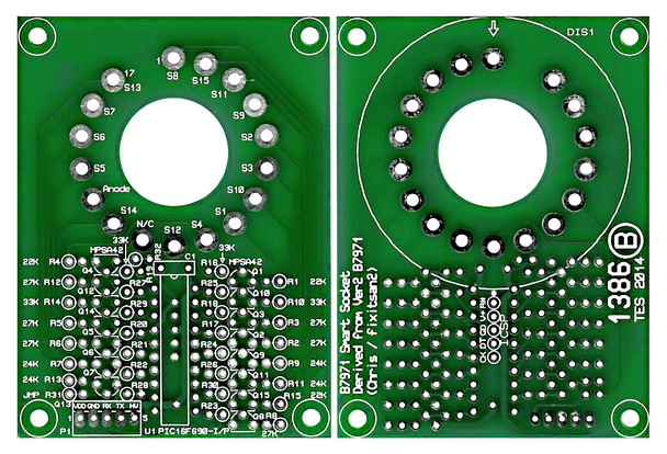
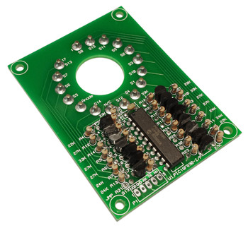
Description
Documents: Schematic / BOM / FW Image / Chain Timing / Chain Enumeration / Protocol
Description: This circuit was created by Chris Barron (Yahoo group fixitsan2) and covered under a generous license agreement. This B7971 14 segment nixie driver board was originally done in the Eagle PCB design program but was redesigned in Proteus CADD for the production PWBs offered here while the circuit itself was changed as little as possible from the original design. A GUI is available for testing the serial communication of smart socket strings and includes a font editor for the B7971 SmartSocket UDC (User Defined Character) feature. You can use the SmartSocket control app to exercise these modules. The protocol is also detailed in the help section of the GUI.
Testing: After assembly, these units are tested on an automated fixture for serial data in and out as well as functionality of each segment driver.
Floating #MCLR (Pin 4): These assemblies have the new R32 installed to pull up the #MCLR pin on the PIC. Before adding this, these modules would be susceptible to ESD and noise.


