Description
Documents: Schematic (RevA Rev-) / BOM (Rev-) / Assembled / Breadboard
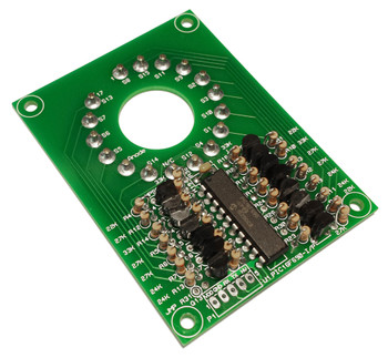
This is a simple hard logic nixie clock based on a data book application schematic from the mid 1970's illustrating the use of Texas Instruments' 74141 BCD-Decimal nixie decoder-driver IC's. A few modifications from the original design were implemented:
Features:
- A 5V series regulator instead of the original zener shunt circuit for powering the logic.
- Neon lamp drive for the AM/PM indicators.
- Zeroing was added to the line frequency prescaler and 1's digit during setting.
- The high voltage transformer input has also been replaced by a boost supply for the anode 170V supply.
- An error in the seconds 10's connection between the decoder and display was corrected.
- Wires for 60Hz line operation. Jumpers are provided for configuration for 50Hz line frequency
Construction:
- All through hole parts except the bypass capacitors which are 1206 ceramic SMT.
- Pads are provided for either an SMT vertical power connector or a through hole right angle power connector.
- Pads are provided for either a 4 pin DIP bridge rectifier or4 single diodes.
- HVPS may be jumper selected to be powered via the raw DC rail or from the 5V regulator output (This improves efficiency when a 5V switcher is used in place of the 7805).
- Designed for IN12 nixie tubes but this will work with any nixie display: The cathodes for each tube are marked on the PWB for easy wiring.
- Components are labeled with their values for easy assembly.
Input power:
- 9VAC @ 500mA, suggested AC output wall adapters and connector, listed below are suitable adapters.
- CUI EPA090050-S/T-SZ, 120VAC in / 9VAC out @ 500mA (Digikey T1004-ND)
- ReliaPro ACU090050, 120VAC in / 9VAC out @ 500mA (Jameco 100061)
- Radio Shack 15-1963, 120VAC in / 12VAC out @ 400mA (Jameco 2076543)
- Check Marlin P Jones for good deals on adapters.


