Description
Schematic , Z80 CPU , Z80 UI , Baud Rates (Source)
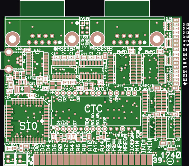
The 1740 uses the Z84C3008PEC CTC and the Z84C4410VEC SIO to implement a 2 channel full duplex RS232 interface for the Z80 computer with independently programmable BAUD rates for each channel. This card also provides a two stage auxiliary timer to interrupt the processor at periods between 30.5uS and 2S (Using a 32.768kHz clock). The output from the first stage of the aux timer is connected to a beeper driver. Finishing off the hardware is a pair of 8 bit output ports connected to 16 LEDs.
Hardware Features:
- 3.0 inch wide by 2.5 inch high 4 layer PWB with a 40 pin (2 x 20 x 0.1) edge mounted female connector to mate with the Z80 Backplane or user circuit.
- Two full duplex RS232 ports; RS232A and RS232B.
- Both ports support hardware hand shaking using the CTS and RTS signals.
- The RS232A port is jumper selectable to connect with either a DSUB-9M connector or an FT232RL USB interface for its RXD and CTS input signals.
- The RS232A port always drives the TXD and RTS signals to both connectors, regardless of the jumper setting.
- The RS232B port connection is implemented with a DSUB-9M connector.
- The DSUB-9M connectors are wired as DTE, i.e. the same pinout as an RS232 port found on a PC for direct connection to devices such as modems. Typically, to connect to a PC directly or via a USB to RS232 cable, a null modem adapter or cable will be needed.
- The DSUB-9M serial ports use MAX232 drivers.
- The Z80 CTC is mapped to I/O ports 0xF4 to 0xF7.
- The Z80 SIO is mapped to I/O ports 0xF8 to 0xFB.
- The two 8 bit output ports for driving the 16 LEDs are mapped to output ports 0xFC and 0xFD.
Baudrate generation
- CTC channel 0 (RS232A) and 1 (RS232B) divide a 3.6864MHz crystal oscillator clock in counter mode to derive the serial port bit clocks or can use the master 8MHz CPU clock in timer mode.
- Using the 3.6864MHz oscillator, baud rates of 300 to 230,400bps can be programmed.
- Using the 8MHz CPU clock, baud rates from 50 to 2400bps can be programmed.
- Note: The CTC will not properly divide the counter mode clock if it is greater than 1/2 the CPU clock.
- Note: The SIO will not transmit or receive serial data while the processor clock is single stepped.
Timer function
- CTC channels 2 and 3 provide the user with a programmable interval timer with interrupt capability.
- Channel 2 is supplied with an on board 32.768kHz clock and then channel 2's output is fed into the input of channel 3.
- In counter mode (Using the 32.768kHz clock) this provides for output intervals ranging from 30.5uS to 2S.
- In timer mode (Using the 8MHz CPU clock) this provides for intervals ranging from 2uS to 2.0972S.
- The output of channel 2 is connected to a D Flip Flop that feeds a beeper driver which can output a signal between 64Hz and 16,384Hz in counter mode or between 61Hz and 250,000Hz in timer mode.


